
TM 5-3805-294-23-4
0611
ASSEMBLY - Continued
14
29
28
27
28
27
26
HYEX01667
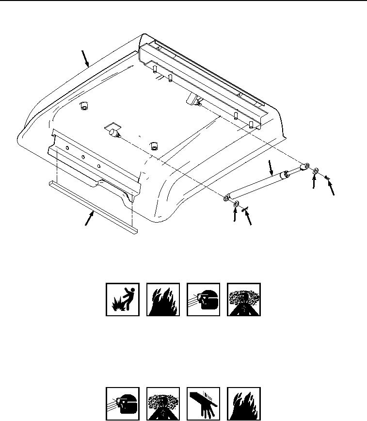
Figure 9.
Ram and Isolator Installation.
WARNING
SOLVENT CLEANING COMPOUND
7.
Clean off any residual isolator material and adhesive from tool box lid (Figure 9, Item 14) using a rag moistened
with solvent cleaning compound.
8.
Wipe area clean and dry to prepare for isolator installation.
WARNING
ADHESIVES AND SEALANTS
9.
Apply adhesive to the back side of isolator (Figure 9, Item 26).
10.
Install isolator (Figure 9, Item 26) to tool box lid (Figure 9, Item 14) and apply pressure.
11.
Install catch (Figure 10, Item 25) to tool box lid (Figure 10, Item 14) with two washers (Figure 10, Item 24) and
screws (Figure 10, Item 23).