
TM 5-3805-294-23-4
0611
DISASSEMBLY - Continued
14
29
28
27
28
27
26
HYEX01667
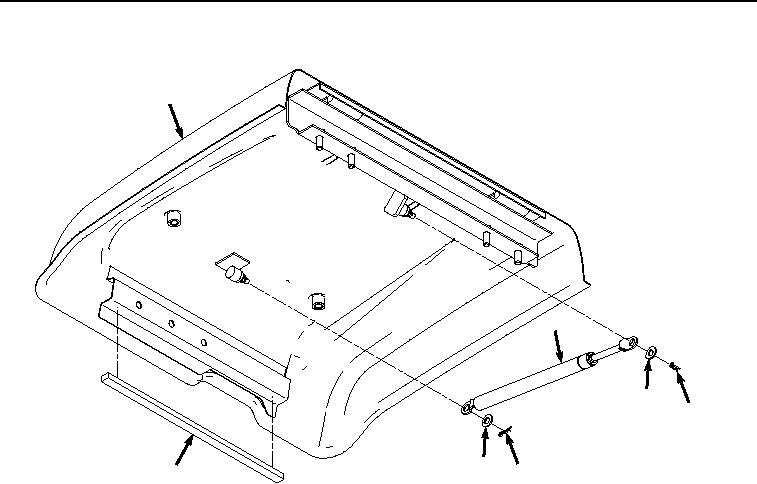
Figure 6.
Ram and Isolator Removal.
8.
Remove two pins (Figure 6, Item 27), washers (Figure 6, Item 28), and ram (Figure 6, Item 29) from tool box
lid (Figure 6, Item 14).
9.
Remove two screws (Figure 7, Item 30), washers (Figure 7, Item 31), and lock assembly (Figure 7, Item 32)
from tool box (Figure 7, Item 8).