
TM 5-3805-294-23-4
0620
DISCONNECT VACUUM PUMP - Continued
17
19
18
13, 14
13, 14
HYEX03314
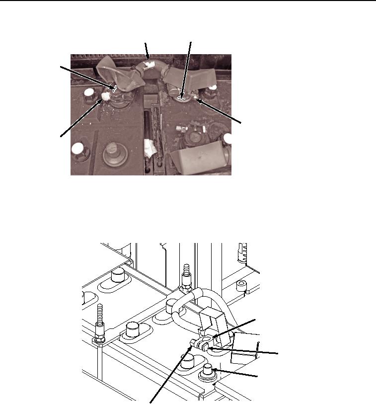
Figure 13. Install Battery Cable.
7.
Tighten two nuts (Figure 13, Item 13) on screws (Figure 13, Item 14) on positive battery cable (Figure 13, Item
17).
8.
Install negative battery terminal clamp (Figure 14, Item 15) to negative battery terminal (Figure 14, Item 16).
15
14
16
HYEX03336
13
Figure 14. Negative Battery Terminal Clamp Installation.
9.
Tighten nut (Figure 14, Item 13) to screw (Figure 14, Item 14) on negative battery terminal clamp (Figure 14,
Item 15).
10.
Install cover (Figure 15, Item 11) to two screws (Figure 15, Item 12) with two washers (Figure 15, Item 10) and
nuts (Figure 15, Item 9).