
TM 5-3805-294-23-4
0621
REMOVAL - Continued
CAUTION
Wipe area clean around all fluid connections prior to removal. Cap and plug all hoses, lines,
fittings, and ports during removal to prevent contamination of system components. Systems
must be kept clean from contaminants. Failure to comply may result in damage to equipment.
NOTE
Place drain pan under valves being removed.
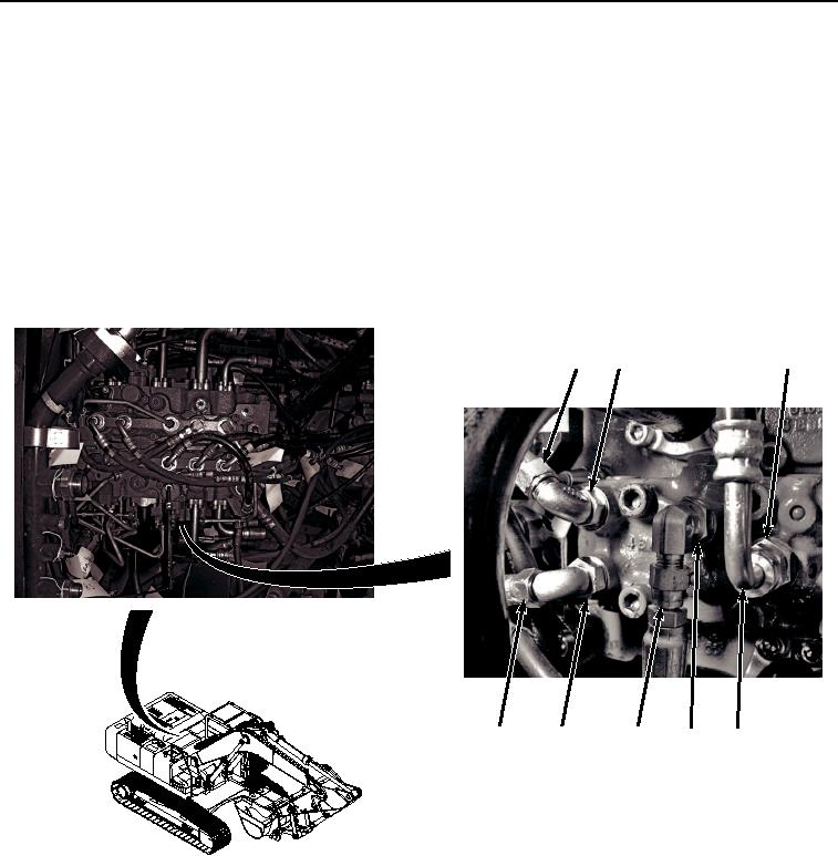
Hoses and components of the main control valve are shown removed for clarity.
Components other than called-out components do not need to be removed.
1.
Remove hose (Figure 1, Item 1) from fitting (Figure 1, Item 2).
5
6
2
8
3
4
1
7
HYEX03372
Figure 1.
Hose Removal.
2.
Remove hose (Figure 1, Item 3) from fitting (Figure 1, Item 4).
3.
Remove hose (Figure 1, Item 5) from fitting (Figure 1, Item 6).
4.
Remove hose (Figure 1, Item 7) from fitting (Figure 1, Item 8).
5.
Remove eight screws (Figure 2, Item 9) and housing (Figure 2, Item 10) from control valve (Figure 2, Item 11).