
TM 5-2420-230-24-1
8-6. BRAKE DRUM REPLACEMENT.
This Task Covers:
a. Removal
b. Cleaning
c. Inspection
d. Installation
e. Adjustment
f. Testing
g. Follow-On Maintenance
INITIAL SETUP
Test Equipment
References
None
TM 9-214
TM 9-2610-200-14
Tools and Special Tools
Tool kit, common no. 2, Item 36, Appendix B
Equipment Conditions
Tool kit, general mechanics, Item 38, Appendix B
TM or Para
Condition Description
Wheel and tire removed.
Materials/Parts
Cloth, lint-free, Item 10, Appendix C
Drawings Required
CRC 5-56, Item 40, Appendix C
TM 5-2420-230-24P Figure 101
Solvent, degreasing, Item 58, Appendix C
TM 5-2420-230-24P Figure 103
Personnel Required
Estimated Time to Complete
MOS 62B, Construction Equipment Repairer (2)
Refer to MAC in Appendix B
NOTE
Maintenance procedures are shown for one
brake drum only, but are performed the
same way for all wheels.
a. Removal.
(1)
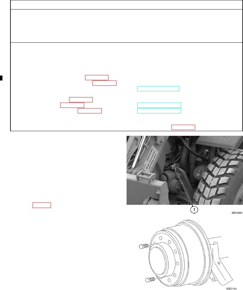
Release parking brake control. If there is
insufficient air in air tanks, connect external
air source to front, left glad hand fitting (1)
or manually cage spring brake chamber
(2)
Rotate brake drum and ensure it rotates
freely without binding on brake shoes.
(3)
Remove all paint from hub with wire brush
and lubricate with CRC 5-56.
(4)
Remove retaining screw from brake drum to
axle hub.
(5)
Install two setscrews into both of tapped
holes until tight. Equally tighten both screws
to remove brake drum.
Change 1