
TM 5-2420-230-24-1
BRAKING SYSTEM
Contents
Para
Page
General. . . . . . . . . . . . . . . . . . . . . . . . . . . . . . . . . . . . . . . . . . . . . . . . . . . . . . . . . . . . . . . . . . . . . . . . .
System Operation - Basic Operation.. . . . . . . . . . . . . . . . . . . . . . . . . . . . . . . . . . . . . . . . . . . . . . . . . .
Vehicle Preparation and Isolation. . . . . . . . . . . . . . . . . . . . . . . . . . . . . . . . . . . . . . . . . . . . . . . . . . . . .
Restore IHMEE to Operational Readiness. . . . . . . . . . . . . . . . . . . . . . . . . . . . . . . . . . . . . . . . . . . . . .
Slack Adjuster Replacement. . . . . . . . . . . . . . . . . . . . . . . . . . . . . . . . . . . . . . . . . . . . . . . . . . . . . . . . .
Brake Drum Replacement. . . . . . . . . . . . . . . . . . . . . . . . . . . . . . . . . . . . . . . . . . . . . . . . . . . . . . . . . . .
Spring Brake Chamber Replacement. . . . . . . . . . . . . . . . . . . . . . . . . . . . . . . . . . . . . . . . . . . . . . . . . .
Spring Brake Chamber Caging. . . . . . . . . . . . . . . . . . . . . . . . . . . . . . . . . . . . . . . . . . . . . . . . . . . . . . .
Foot Treadle Valve Replacement. . . . . . . . . . . . . . . . . . . . . . . . . . . . . . . . . . . . . . . . . . . . . . . . . . . . .
Parking Brake Control Replacement.. . . . . . . . . . . . . . . . . . . . . . . . . . . . . . . . . . . . . . . . . . . . . . . . . .
This section contains procedures that relate to
maintenance activities detailed in Chapter 3, Preventive
Maintenance Checks and Services (PMCS). This chapter
should be read in conjunction with Appendix J.
Components covered within this section include:
Brake drum and mechanism
Brake mechanism adjustment
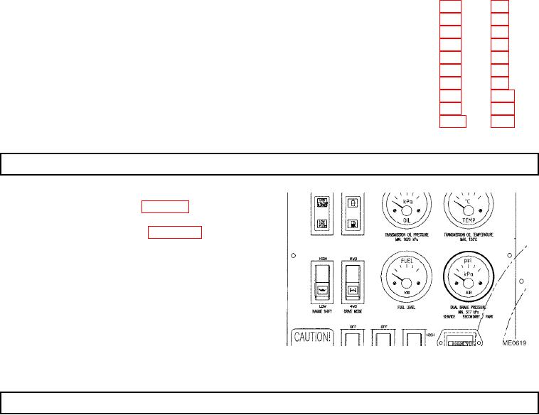
The DUAL BRAKE PRESSURE gauge has two
pointers, one white and one green. The white pointer is
for service air and the green pointer is for park/secondary
air.
8-2. SYSTEM OPERATION - BASIC OPERATION.
a. General. The brake system consists of four spring brake chambers, with one at each wheel. The engine-driven
compressor has an integral governor set at 119 psi (820 kPa).
b. Primary System. When the foot brake pedal is depressed, air pressure is directed from the reservoirs, through the foot
valve, to the spring brake chambers. Air pressure acts on the pneumatic diaphragm, which pushes the chamber rod. The
chamber rod is connected to the slack adjuster and a shaft. This shaft operates the S-cam, which in turn brings the brake
linings into contact with the brake drum, thus providing braking action.
The amount of braking action is directly proportional to the amount of effort applied to the foot brake pedal. As more
pressure is applied to the foot brake pedal, more air pressure is directed to the brake chambers, and more braking action
is applied to the vehicle. The system is provided with a pressure-reducing valve to prevent rear wheel lockup due to
weight transfer as the brakes are applied.