
TM 5-2420-230-24-1
Spicer Speciality Axle Division - Technical Publications
SECTION 28
FINAL ASSEMBLY
28.1
Refill drive head with oil (see lubrication section at front of manual for details of specification and
quantity).
28.2
Refit road wheels, securing with wheel nuts (1).Tighten nuts to 475 - 525 lbs. ft. (644 - 712 Nm).
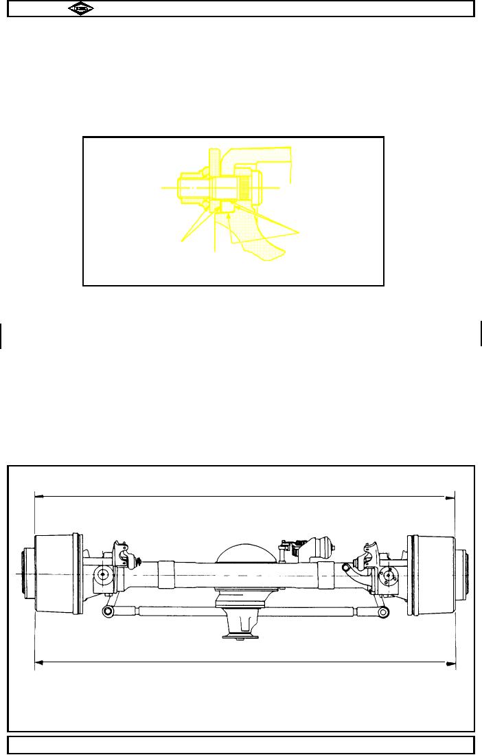
Note :-
Interfaces must be free from dirt , including liner material debris, rust and paint.
Failure to keep interfaces clean, can and will cause brake drum to distort upon
tightening of wheel nuts. For further details see BS AU50 : Part 2 : Section 7A : 1995.
TP1148
Clean interfaces
Clean interfaces
Fig. No. 36
28.3
Remove axle supports, then lower vehicle to ground.
28.4
Remove chocks and jacks.
Note :-
At the axle build, tracking is set to TD 186/1 i.e 'Toe Out'. However, where part time all
wheel drive is used the axle should be re-aligned to 'Toe In' as below:-
28.5
Check wheel alignment as follows :-
Set wheels in a straight ahead position, and at points level with wheel centre, measure distance
between edges of wheel rims both in front and behind axle centre.
For correct alignment front measurement (` A') shoul be 0" to 1/16 " smaller than that of rear (` B')
d
ie. toe -in. To allow for inaccuracies in wheels, same checks should be made with vehicle moved so that
wheels have moved a further half a revolution (see fig no. 37).
Adjust if required by slackening ball joint clamp bolts and rotating track rod tube.
DO NOT forget to re-tighten clamp bolts to 51 - 62lbs.ft. (69 - 84Nm.) after adjusting.
TP64
'A'
Front
'B'
Measure dimns. 'A '& 'B 'over brake drums
on horizontal centre line
To give correct alignment dimn 'A' should
be 1/16" smaller than dimn 'B'.
Fig No. 37
Manual No. 1785 Issue B
A
Page No.B32
Spicer Speciality Axle Division
J-62