
TM 5-2420-230-24-1
Spicer Speciality Axle Division - Technical Publications
SECTION 10
FINAL ASSEMBLY OF BRAKE Cont
10.4
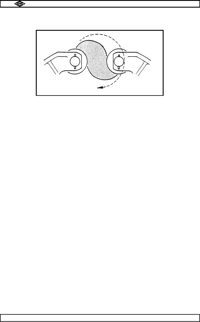
Seat brake shoe rollers (37) in position on brake cam (23) so that they lie in depressions, see fig 5.
This ensures that cam is in its correct operating position.
TP 41
Fig. No.5.
10.5
Refit brake shoe anchor pin split pin (70) and position anchor pin (69) into brake shoe (66).
10.6
Hook brake shoe return spring (24) onto brake shoe anchor pin (69), then expand with a spring bar or
1
/2 " blade screwdriver to position on to brake bracket anchor pin (25).
10.7
Repeat operations 10.5 and 10.6 to fit other brake shoe return spring (24) to other brake shoe (66).
10.8
Fit slack adjuster as follows :-
a)
Check that brake chamber push rod is in its fully released position.
b)
Smear brake camshaft and slack adjuster splines (23 & 49) with BP Keenomax L2 or
equivalent grease.
c)
Fit slack adjuster (49) onto brake camshaft splines (24) in its original marked position.
d)
Screw clevis onto brake chamber push rod to its original marked position, then secure
with locknut.
e)
Fit clevis pin and secure in position with split pin.
10.9
Fit cam end spring (50), followed by washer (51) and circlip (52) onto camshaft (23).
Page No.D10
Manual No. 1785 Issue A
Spicer Speciality Axle Division
J-102