
TM 5-2420-230-24-1
Adjust Automatic Relief Plungers
Automatic relief plungers require no adjustment unless tire size is changed or wheel cut is reduced. A relief
plunger is located in each end cap of the steering gear - one for right turn; one for left turn. Automatic relief
plungers have plastic caps over the plunger hole on each end.
TOOLS REQUIRED:
1/4" Punch
Ball Peen Hammer
WARNING
FOR OTHER EQUIPMENT, TOOLS OR SAFETY PROCEDURES, ALWAYS
F O L L OW THE VEHICLE MANUFACTURER'S INSTRUCTIONS FOR
LIFTING AND BLOCKING.
ADDITIONAL REFERENCES:
Vehicle Manufacturer's Service Manual
NOTE:
Do not attempt to set automatic relief plungers until the axle stops have been set
according to Vehicle Manufacturer's specifications.
PROCEDURE:
1.
Park the vehicle on a clean, dry surface (preferably concrete). Place the transmission in neutral and set the
parking brake.
2.
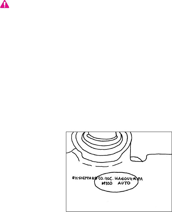
Verify that the steering gear you are working on is equipped with automatic relief plungers. Steering gears
with automatic pressure relief plungers will have "M100 AUTO" cast in raised letters on the cylinder bore.
Plastic caps over the plunger holes are installed as a visual aid in recognizing auto plunger steering gears.
(Figure 37).
Figure 37
K-50