
TM 5-2420-230-24-1
NOTE:
The plunger flange is held in place with patch
lock and the threads are staked. Removal of
the flange will require approximately 12-15
in/lbs of torque.
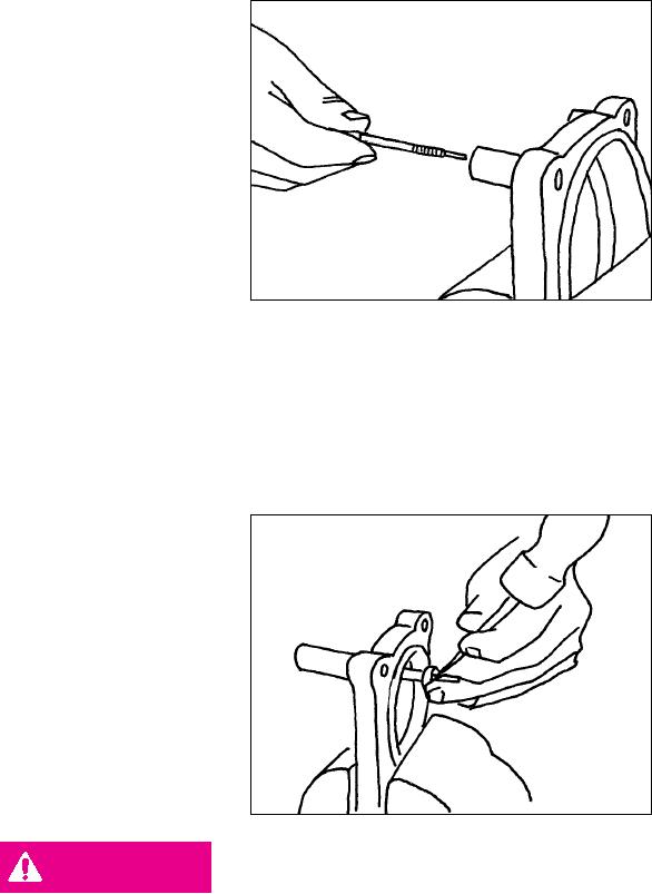
6. Remove the plunger body from the spring
pin. It may be necessary to lightly tap the
plunger body to remove it from the spring pin.
Use of an 1/8" pin punch is recommended.
(Figure 42).
7. Coat the O-ring with a light coat of grease
Figure 42
and install the new plunger body through the
spring pin.
NOTE:
Inspect the plunger bore for nicks or gouges
before installing the plunger body.
8. Use the screwdriver to hold the plunger body
and screw the plunger flange onto the plunger
body until it contacts the spring pin.
NOTE:
It will be necessary to use the locking pliers to
turn the plunger flange over the patch lock.
Installation of the plunger flange will require
approximately 12-15 in/lbs of torque.
9.
With the plunger flange against the spring
pin, use a center punch and hammer to stake
the threads of the plunger body.(Figure 43).
Figure 43
DANGER
USE EXTREME CAUTION WHEN STAKING THE THREADS OF THE
PLUNGER BODY. HITTING THE THREADS TOO HARD WILL BEND THE
PLUNGER AND CAN CAUSE STEERING FAILURE.
10.
Align the cylinder head marks and install the cylinder head on the steering gear. Torque the attaching bolts
to the recommended specifications.
11.
Fill the reservoir with an approved fluid. Start the engine and check for leaks.
12.
Raise the front wheels and turn the steering wheel from lock to lock to set the auto plungers.
13.
Lower the vehicle.
K-53