TM 5-2420-230-24-1
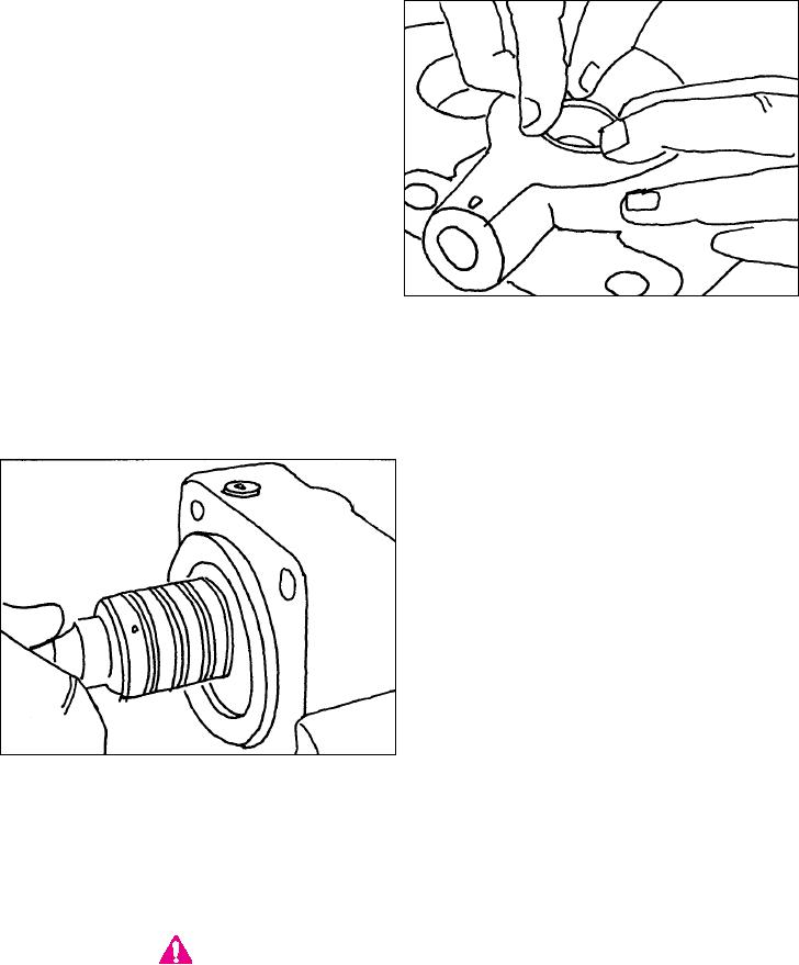
15. Press the salt seal into the cap until it is flush
with the bearing cap. Pack the area between
the oil and salt seal with grease.(Figure 75).
Figure 75
16. Clamp the bearing cap in the vise.
17. Inspect the rotary valve seals to insure there are no nicks or cuts. If rotary valve seal installation is necessary,
refer to "Rotary Valve Seal Replacement" in the Common Procedures section of this manual. Tape the
splines of the input shaft to prevent seal damage during installation.
18. Review Figure 76 and insure the thrust
washers and roller bearings are installed on
the shaft properly.
Figure 76
NOTE:
A light coat of grease on the thrust bearings and thrust washers will help to keep
them in place during installation.
19. Install the input shaft assembly in the bearing cap.
CAUTION
Care must be taken during installation of the input shaft assembly to prevent damage
to rotary valve seals, thrust washers and thrust bearings. Do not turn the shaft during
installation.
K-69

