
TM 5-2420-230-24-1
6.
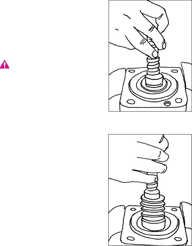
Reposition the assembly in the vise.
7.
Carefully slide the valve shaft out of the
bearing cap. Do not turn the shaft when
removing (Figures 67 & 68).
CAbe usedIONremoving the shaft
UT when
Care must
assembly from the bearing cap to insure that
rotary valve seals, thrust washers and roller
bearings are not damaged.
NOTE:
Do not remove the rotary valve seals and
energizing O-rings from the valve shaft.
Figure 67
Replacement of these seals is not necessary,
unless the original seals were damaged dur-
ing shaft removal.
Figure 68
K-66