
TM 5-2420-230-24-2
Valve Clearance - Adjustment (0-103)
Section 0 - Engine Disassembly and Assembly - Group 00
Page 0-98
B Series Shop Manual
Feeler Gauge
Valve Stem to Rocker Lever Clearance
Intake Valve
Exhaust Valve
0.254 mm
0.508
[0.010 in]
[0.020 in]
The clearance is correct when some resistance can be
``felt'' when the feeler gauge is pulled through the space
between the valve stem and rocker lever.
Adjust the valves as indicated in the following illustrations.
Tighten the locknuts and check the clearance again.
Torque Value: 24 Nm
[18 ft-lb]
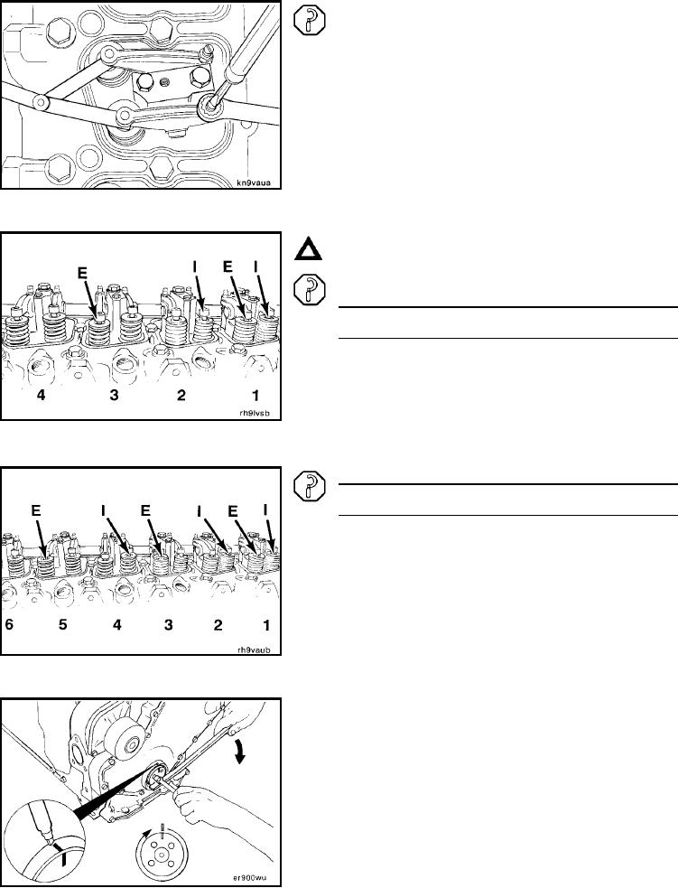
Caution: Perform step A of the valve set procedure with
Cylinder Number 1 at TDC compression stroke (timing
pin will engage).
Step A - Four Cylinder
Valve
Cylinder
I = Intake
E=
Exhaust
1
*
*
2
*
-
3
-
*
4
-
-
(* = Set)
(- = Do not Set)
Step A - Six Cylinder
Valve
Cylinder
I = Intake
E = Exhaust
1
*
*
2
*
-
3
-
*
4
*
-
5
-
*
6
-
-
(* = Set)
(- = Do not Set)
Perform Step B of the valve set procedure with Cyl-
inder Number 1 at TDC plus 360 degrees (timing pin
will not engage).
Mark the crankshaft and front cover. Rotate the crankshaft
one full turn.
L-187