
TM 5-2420-230-24-2
Section 0 - Engine Disassembly and Assembly - Group 00
Injector Nozzles - Installation (0-104)
B Series Shop Manual
Page 0-99
Step B - Four Cylinder
Valve
Cylinder
I = Intake
E = Exhaust
1
-
-
2
-
*
3
*
-
4
*
*
(* = Set)
(- = Do not Set)
Step B - Six Cylinder
Valve
Cylinder
I = Intake
E=
1
-
-
2
-
*
3
*
-
4
-
*
5
*
-
6
*
*
(* = Set)
(- = Do not Set)
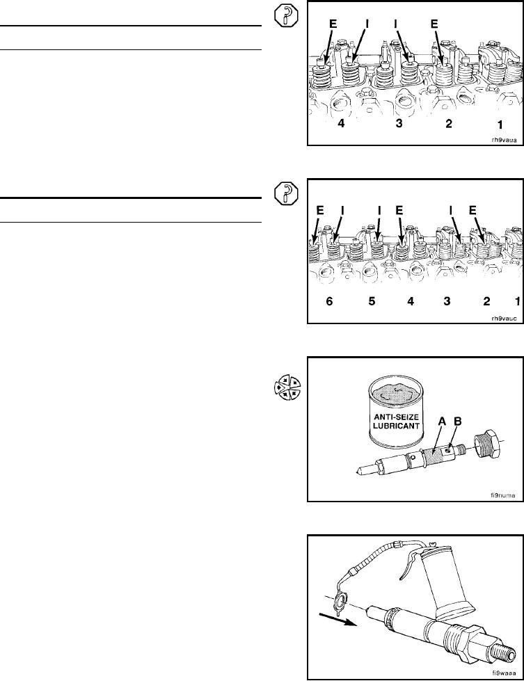
Injector Nozzles - Installation (0-104)
Apply a coat of anti-seize compound to the threads of the
injector hold-down nut and between the top of the nut and
injector body (A). Avoid getting anti-seize compound in
the fuel drain hole (B).
Assemble a sealing washer on each injector.
Use only one sealing washer.
NOTE: A light coat of clean 15W-40 engine oil between the
washer and injector can help to keep the washer from falling
during installation.
L-188