
TM 5-2420-230-24-2
Section 0 - Engine Disassembly and Assembly - Group 00
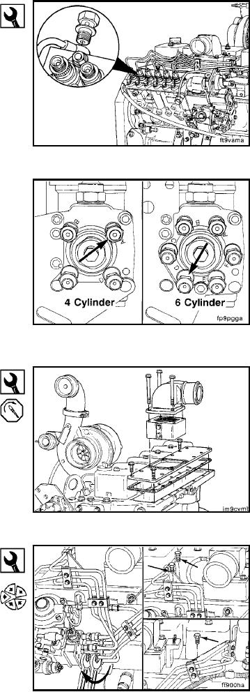
Fuel Lines - Installation (0-108)
B Series Shop Manual
Page 0-103
19 mm
Connect the Bosch P7100 injection pump vent.
Torque Value: 32 Nm
[24 ft-lb]
High Pressure Fuel Lines - Installation (0-110)
Assemble the high pressure fuel lines.
The number one cylinder delivery valve is marked on the
pump as illustrated.
4 cylinder = A
6 cylinder = D
Firing Order
4 Cylinder
6 Cylinder
A=1
D=1
B=3
E=5
C=4
F=3
D=2
A=6
B=2
C=4
13 mm
Tighten all of the manifold cover capscrews.
Torque Value: 24 Nm
[18 ft-lb]
14 mm, 17 mm
Make sure that the high pressure lines will not rub against
other engine components.
Tighten the high pressure lines at the injection pump and
injectors securely.
Torque Value: 24 Nm
[18 ft-lb]
L-192