
TM 5-2420-230-24-2
Cylinder Head (002-004)
B3.9 and B5.9 Series Engines
Page 2-18
Section 2 - Cylinder Head - Group 02
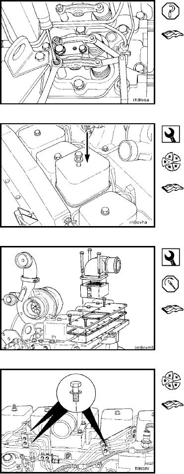
Valve Clearance - Adjustment
Adjust the valve clearance. Refer to Procedure 003-004.
15 mm
Install the rocker lever cover(s). Refer to Procedure 003-
011.
Tighten the capscrews.
10 mm
Install the manifold cover plate. Refer to Procedure 010-
023.
Install the fuel filter head to the air intake manifold.
Install intake heater (if equipped). Refer to Procedure 010-
072.
Use the illustrated capscrews to secure the cover plate. The
remaining holes are used to secure fuel line brackets.
Torque Value: 24 Nm
[18 ft-lb]
Install the injectors and fuel lines. Refer to Procedures
006-026 and 006-051.
L-814