
TM 5-2420-232-10
0055
LOAD MACHINE
00055
1.
Start loader engine and allow to warm up (WP 0005).
2.
Lower the suspension to the Transportation/Limp-home mode (WP 0004).
3.
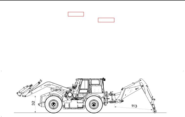
Raise loader arm to set the center of the quick-hitch to loader arm pivot pin to 32 in. above the ground (Figure 6).
CAUTION
Raising the loader arms too high may cause part of the loader assembly to contact the aircraft
during loading. Damage to the aircraft may result.
4.
Set the quick-hitch to its fully crowded back position (Figure 6).
5.
Set the excavator end to the correct dipper position, 113 in. between boom/kingpost pivot pin and tipping link/dipper pivot
pin centers (Figure 6), and release the slew lock pin.
435-A1785
Figure 6. Loader Height and Dipper Setting Out Position
055
Change 1
0055-10