
TM 5-2420-232-10
0055
LOAD MACHINE CONTINUED
WARNING
Always use a ground guide when operating machine up or down ramps. Failure to use a ground
guide may cause injury or death to personnel or damage to equipment.
Drive with extreme caution, at low idle, and in 1st REVERSE gear ONLY. Failure to follow this
warning may cause injury or death to personnel or damage to equipment.
NOTE
From this point on lift the excavator end only by the boom cylinder to preserve the correct dipper
setting out position of 113 in.
6.
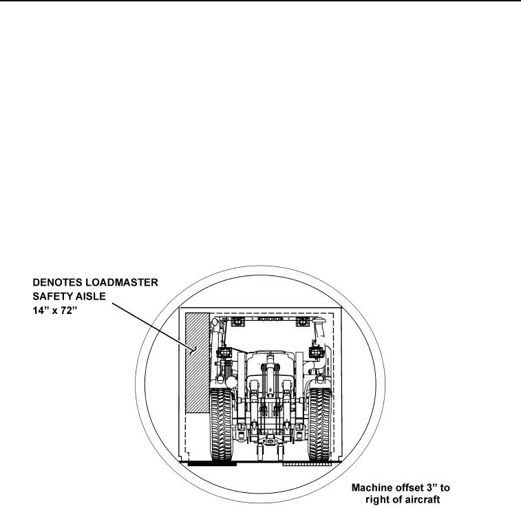
Using ground guide assistance and in 1st gear reverse ONLY, SLOWLY reverse the machine towards the loading ramp of
the aircraft with the backhoe extended out behind the machine. Note that the machine is to be loaded offset 3 in. to the
right of the aircraft center line in order to leave the necessary 14 in. Loadmaster Safety Aisle on the left (Figure 7). Lift the
excavator end by the boom control only so dolly wheels are slightly above the height of the floor in main carriage bay
(Figure 8, Sequence 1).
435-A1786
Figure 7. Loading Offset from Center Line
055
0055-11
Change 1