
TM 5-2420-232-10
0055
LOAD MACHINE CONTINUED
7.
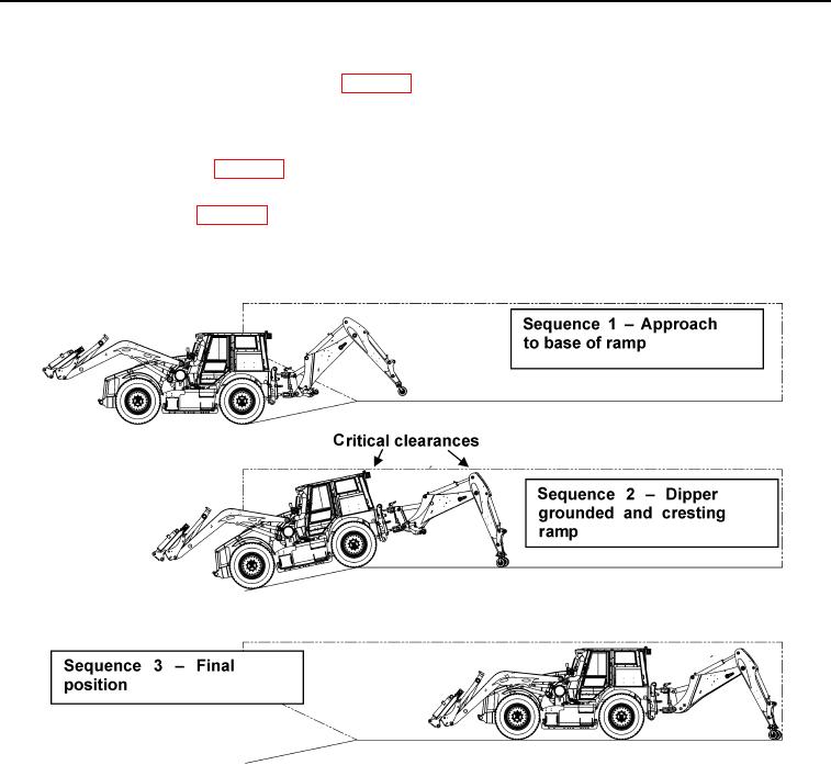
Once the backhoe dipper dolly is inside the airframe, and before the rear wheels of the machine contact the entrance ramp,
bring the vehicle to a halt, apply the parkbrake (WP 0004) and slew the excavator end slowly to the right until the dipper
dolly wheels are above the aircraft s right side treadway. Lower the boom slowly so that the dipper dolly wheels JUST
make contact with the treadway (Figure 8, Sequence 2). Do not operate dipper ram; the 113 in. dimension (Figure 6) must
be maintained to control the height of the dipper.
8.
Operate the boom float valve (WP 0004) so that the boom assembly can "float." The dipper dolly now supports part of the
weight of the backhoe.
9.
Release the parking brake (WP 0004) and, following the load master s instructions, VERY SLOWLY reverse the machine
into the aircraft, ensuring that the dipper dolly continues to advance along the treadway. As the machine s rear axle crests
the ramp, check the critical clearances above the rear of the cab and the top of the dipper (Figure 8, Sequence 2).
435-A1787
Figure 8. Loading Sequence and Critical Clearances
055
Change 1
0055-12