
TM 5-3805-280-24-2
Removal and Installation
IMPORTANT: Visually inspect contact surfaces of
valve tips and rocker arm wear pads.
Check all parts for excessive wear,
breakage, or cracks. Replace parts that
show visible damage.
Rocker arms that exhibit excessive
valve clearance should be inspected
more thoroughly to identify damaged
parts.
04
0400
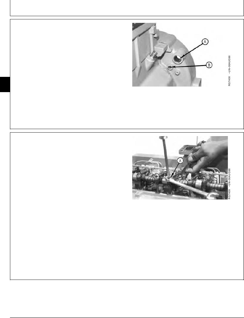
2. Remove plug (A). Install JDG820 Flywheel Turning
20
Tool. Remove cap screw (B). Install JDE81-4 Timing
A--Plug
Pin.
B--Cap Screw
TX,04,UU3877
1918SEP982/4
3. Turn flywheel until timing pin goes into hole in flywheel.
4. Using engine rotation tool, rotate engine flywheel in
running direction (clockwise viewed from front) until No.
1 cylinder is at "TDC" Compression stroke.
If No. 1 cylinder rocker arms are loose, the engine is at
No. 1 "TDC" Compression. If No. 1 cylinder rocker
arms are not loose, rotate engine one full revolution
(360) to No. 1 "TDC" Compression
To change piston position, remove timing pin and
rotate flywheel.
A--Jam Nut
5. Check and adjust valve clearance to specifications as
directed in the following procedures.
6. Loosen jam nut (A) and adjust clearance with a
screwdriver, as shown.
Continued on next page
TX,04,UU3877
1918SEP983/4
13-20