
TM 5-3805-280-24-2
Crankshaft, Main Bearings and Flywheel
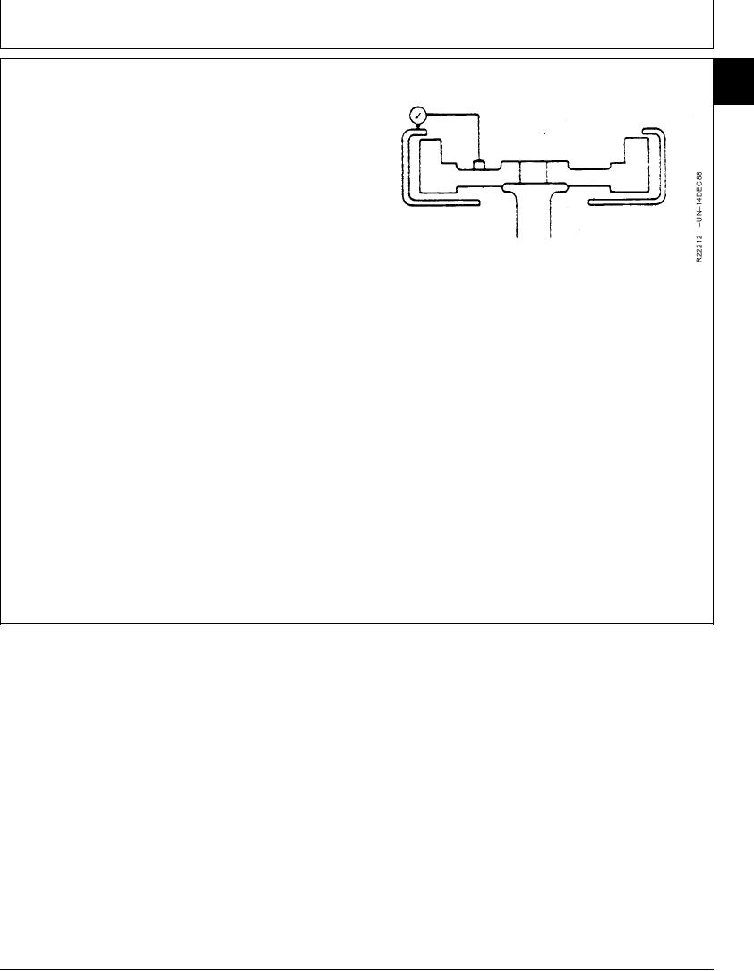
CHECK FLYWHEEL HOUSING FACE
15
23
RUNOUT
1. Mount dial indicator on flywheel. Set pointer to contact
PTO mounting surface on flywheel housing and at right
angles. Pointer should not contact holes in flywheel
housing.
2. Preload indicator tip. Set dial indicator to 0.0 mm (in.).
IMPORTANT: Maintain constant end pressure on
crankshaft to hold shaft against thrust
bearing when measuring flywheel
housing face runout.
3. Rotate flywheel by turning crankshaft. Read total dial
indicator movement. It should not exceed
specifications.
Flywheel Housing--Specification
Maximum Face Runou (12......................................... 0.30 mm (0.012 in.)
O'Clock)
Maximum Face Runout (3 and 9 ............................... 0.25 mm (0.010 in.)
O'Clock)
4. If runout exceeds specifications, resurface flywheel
housing face or replace housing as necessary.
DPSG,OUO1004,214
1909JUL981/1
13-201