
TM 5-3805-280-24-2
Fuel System
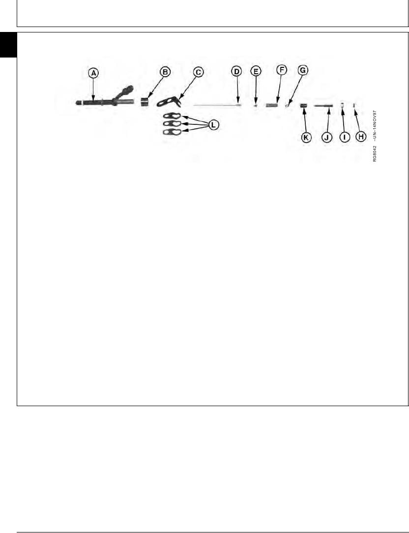
ASSEMBLE FUEL INJECTION NOZZLES
35
74
A--Nozzle Body
E--Spring Seat
H--Lift Adjusting Screw
J--Lift Adjusting Screw
B--Spacer
F--Pressure Adjusting
Lock Nut
K--Pressure Adjusting
C--Indexing Clamp
Spring
I--Pressure Adjusting
Screw
D--Nozzle Valve
G--Washer
Screw Lock Nut
L--Hold-Down Clamps
4. Invert adjusting screw assembly and assemble
1. Install nozzle spacer (B) onto upper nozzle body
spring seat (E) and spring (F) to adjusting screw.
(A). Position nozzle locating clamp (C) over upper
nozzle body with flanges pointing downward. Install
5. Tilt body, DO NOT allow valve to fall out, and install
three remaining clamps (L) onto nozzle body.
spring and adjusting screws to body. Be careful not
to dislodge spring or seat during initial assembly.
IMPORTANT: Wear rubber gloves when
assembling nozzles.
6. Turn pressure adjusting screw down as far as
possible by hand; usually about ten full turns.
2. Dip valve (D) in clean fuel and insert into nozzle
Adjust nozzle as detailed later in this group.
body.
3. Thread lift adjusting screw (J) into pressure
adjusting screw (K) until top just enters screw.
RG,35,JW7587
1920NOV971/1
13-453