
TM 5-3805-281-24-2
Removal and Installation
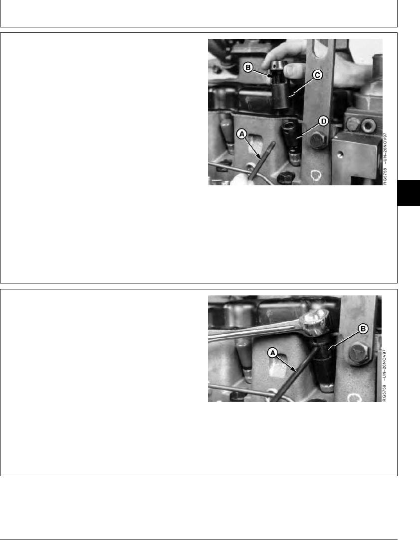
6. Position inner socket (D) over nozzle holder and
engage with flats at top of nozzle holder.
7. Place outer socket (C) portion of JDE92 Nozzle Socket
on gland nut with socket "window" (B) facing outward.
8. Insert handle (A) through window into inner socket. Ball
detent in handle will keep it secured to inner socket.
NOTE: Handle simulates position of leak-off connector,
which must be square with engine to permit
proper installation of leak-off lines.
04
0400
31
A--Handle
B--Window
C--Outer Socket
D--Inner Socket
CED,OUOE024,211
1918MAY983/7
9. Tighten injection nozzle gland nut. Keep handle (A)
pointing straight out while tightening.
Fuel Injection Nozzle Gland Nut--Specification
Torque ............................................................................. 88 Nm (65 lb-ft)
Socket window (B) is cut deep enough to obtain a new
"bite" without removing inner socket.
10. Be sure O-ring is positioned against injection nozzle
gland nut.
A--Handle
B--Socket Window
Continued on next page
CED,OUOE024,211
1918MAY984/7
11-31