
TM 5-3805-281-24-2
Cylinder Head and Valves
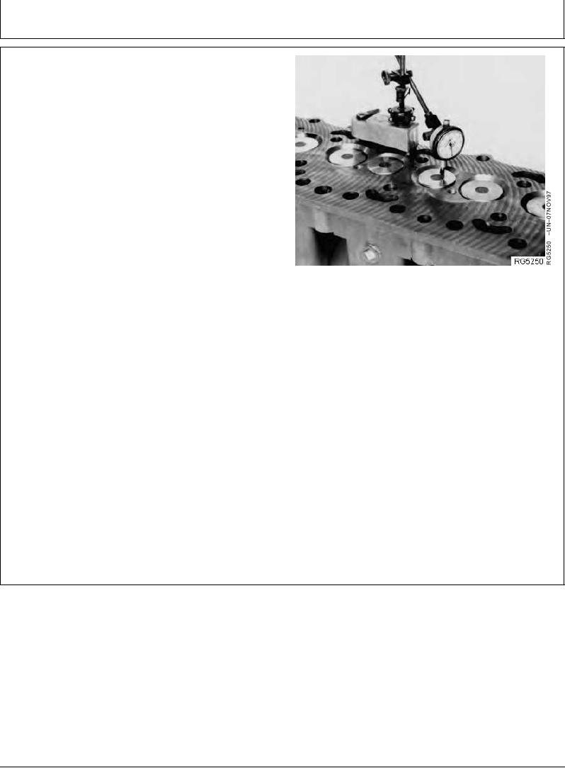
MEASURE VALVE RECESS
Measure and record valve recess dimensions for all
valves using JDG451 Gauge with D17526CI (English, in.)
or D17527CI (Metric, mm) Dial Indicator or KJD10123
Gauge. Compare measurements to specifications given
below.
Exhaust Valve--Specification
Recess................................................. 1.19--1.70 mm (0.047--0.067 in.)
below cylinder head
Recess........................................................ 2.46 mm (0.097 in.) maximum
below cylinder head
Intake Valve--Specification
Recess...................................................... 3.345--3.86 mm (0.132--0.152
Measuring Valve Recess
in.) below cylinder head
Recess........................................................ 4.62 mm (0.182 in.) maximum
below cylinder head
NOTE: Thoroughly clean all gasket material from cylinder
head combustion face before measuring.
If measurement does not meet specifications,
check valve face angle and valve seat angle. If
valve is recessed beyond the maximum
specification, install either new valves, valve seat
inserts, or both to obtain proper valve recess.
(See REMOVE VALVE SEAT INSERTS AND
MEASURE BORES IN CYLINDER HEAD, later in
this group.)
RG,RG34710,1077
1923OCT971/1