
TM 5-3805-281-24-2
Cylinder Head and Valves
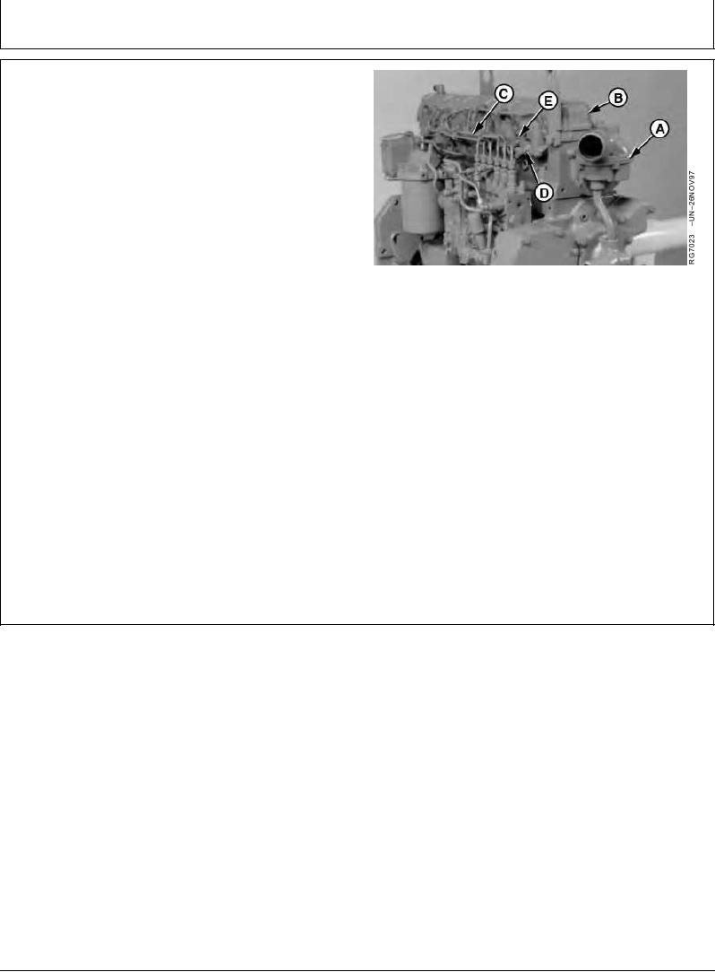
COMPLETE FINAL ASSEMBLY OF
INJECTION PUMP SIDE OF ENGINE
1. Adjust valve clearance, if not previously done.
NOTE: Apply AR31790 SCOTCH-GRIP Adhesive or
equivalent to seal gasket to rocker arm cover (B).
Follow manufacturer's directions on the package
for correct application procedure and curing time.
2. Position rocker arm cover gasket on cylinder head and
install rocker arm cover. Tighten cap screws to 8 Nm
Final Assembly of Injection Pump Side of Engine
(6 lb-ft) (72 lb-in.).
A--Water Manifold
3. Install fuel injection nozzles (E), fuel leak-off lines (D)
B--Rocker Arm Cover
and fuel delivery lines (C). (See INSTALL FUEL
C--Fuel Delivery (Pressure) Lines
INJECTION NOZZLES in Group 35.)
D--Fuel Leak-off Lines
E--Fuel Injection Nozzles
4. Connect ventilator outlet hose to adapter on rocker arm
cover and tighten clamp securely.
5. Install water manifold (A). (See INSTALL WATER
MANIFOLD in Group 25.)
SCOTCH-GRIP is a trademark of 3M Co.
RG,RG34710,1105
1923OCT971/1