
TM 5-3805-281-24-2
Cylinder Head and Valves
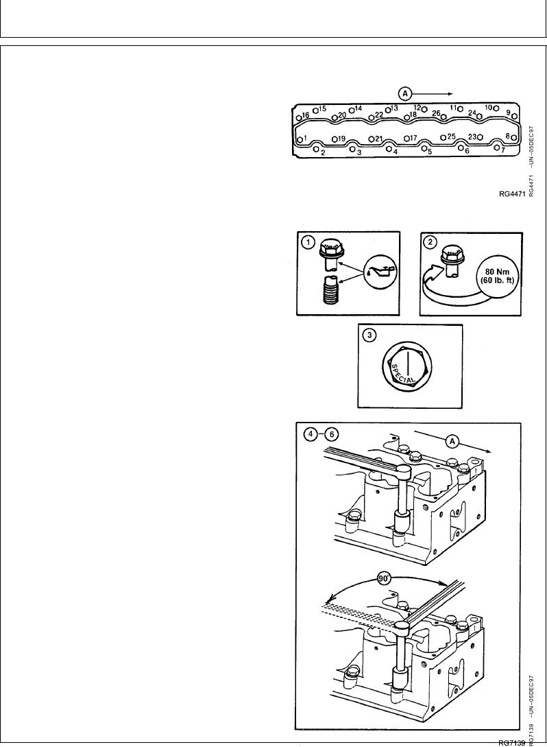
TORQUE-TO-YIELD FLANGED-HEAD CAP
SCREWS--GRADE 180 MARKED "SPECIAL"
Arrow (A) points toward front of engine.
IMPORTANT: DO NOT use multi-viscosity oils to
lubricate cap screws.
1. Lubricate cap screws with clean SAE30 engine oil and
install in their proper locations as outlined previously.
2. Tighten cap screw No. 17 to 80 Nm (60 lb-ft).
Sequentially (start at cap screw No. 1 and proceed
Head Cap Screw Locations
through cap screw No. 26) tighten all cap screws to 80
Nm (60 lb-ft).
3. Using an oil-proof pen, pencil, or marker, draw a line
parallel to the crankshaft across the entire top of each
cap screw head. This line will be used as a reference
mark.
IMPORTANT: If a cap screw is accidentally tightened
more than 90 in any one sequence, DO
NOT loosen cap screw but make
adjustments in the next tightening
sequence.
4. Sequentially (start at cap screw No. 1 and proceed
through cap screw No. 26) turn each cap screw 90.
Line on top of cap screw will be perpendicular to
crankshaft.
5. Again, sequentially (start at cap screw No. 1 and
proceed through cap screw No. 26) turn each cap
screw 90. Line on top of cap screw will now be
parallel to crankshaft.
6. Finally, sequentially (start at cap screw No. 1 and
proceed through cap screw No. 26). Turn each cap
screw 90, SO THAT LINE ON TOP OF CAP SCREW
IS AS CLOSE AS POSSIBLE TO BEING
PERPENDICULAR TO THE CRANKSHAFT. It is not
necessary to obtain the final turn in one swing of the
wrench. TOTAL AMOUNT OF TURN FROM STEPS 4,
5, AND 6 IS 270 5.
Continued on next page
RG,RG34710,1103
1923OCT971/2
Torque-to-Yield Tightening of Head Cap Screws