
TM 5-3805-281-24-2
Cylinder Block, Liners, Pistons, and Rods
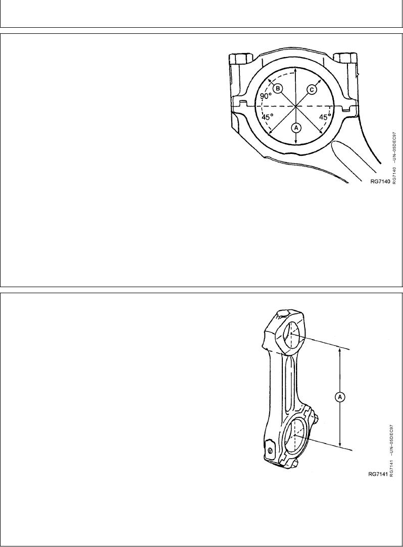
7. Using an inside micrometer, measure rod bore at
center of bore and record measurements as follows:
At right angle to rod/cap joint (A).
At 45 left of measurement step "A" (B).
At 45 right of measurement step "A" (C).
Rod Bore--Specification
ID ............................................................................... 81.051--81.077 mm
(3.191--3.192 in.)
8. Compare the measurements. If difference between the
greatest and least measurement is more than 0.04 mm
(0.0016 in.), the rod and cap are out-of-round. Replace
both connecting rod and cap.
Measuring Connecting Rod and Cap Bore
RG,RG34710,1128
1923OCT972/3
9. Measure rod's piston pin bore-to-crankshaft bore
center-to-center dimension (A) and compare with
specification given. If measurement is not within
specification, replace rod.
Centerline of Piston Pin Bore-to-Crankshaft Bore--Specification
Dimension.................................................................. 222.20--222.30 mm
(8.748--8.752 in.)
Measuring Pin Bore-to-Crankshaft Bore
RG,RG34710,1128
1923OCT973/3
11-170