
TM 5-3805-281-24-2
Cylinder Block, Liners, Pistons, and Rods
REMOVE PISTON PIN BUSHING, CLEAN AND
INSPECT PIN BORE
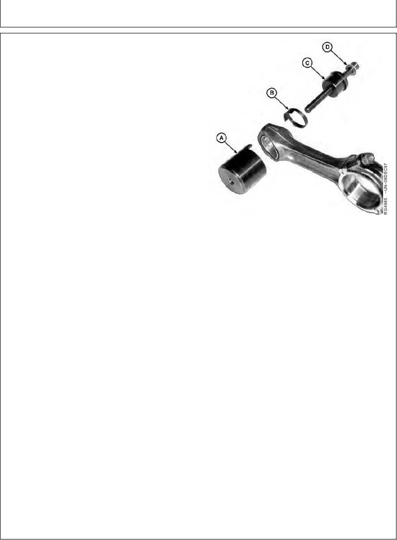
1. If necessary, remove pin bushing with the JDG337 and
JDE98A Connecting Rod Bushing Service Sets.
Use the following tools from the service sets:
JDG339 Cup (A)
JDG338 Adapter (B)
JDE98-4 Driver (C)
STD36104 Forcing Screw with Washer (D)
IMPORTANT: Use care to properly align the JDE98-4
Driver with bushing so that the
connecting rod bushing bore is not
damaged.
2. Clean rod bushing bore using a medium grit emery
cloth, as burrs will distort bushing. Install bushing on
Removing Piston Pin Bushing from Rod
opposite side of rod burr.
A--JDG339 Cup
B--JDG338 Adapter
IMPORTANT: If piston pin bushing bore diameter in
C--JDE98-4 Driver
rod is not within specification or
D--STD36104 Forcing Screw With Washer
bushing has spun in rod, discard rod
and replace with a new one.
3. Measure rod bushing bore in three places
approximately 45 apart. Compare the measurements
with the specifications given below:
Rod Pin Bore--Specification
Diameter without Bushing ......................................... 52.354--52.380 mm
(2.0612--2.0622 in.)
Rod Pin Bore-to-Bushing--Specification
Press Fit ........................................................................ 0.084--0.147 mm
(0.0033--0.0058 in.)
Installed Service Rod Pin Bushing--Specification
ID before Boring ............................................................ 47.58--47.63 mm
(1.8732--1.8751 in.)
ID after Boring ........................................................... 47.655--47.681 mm
(1.8762--1.8772 in.)
RG,RG34710,1130
1923OCT971/1