
TM 5-3805-281-24-2
Fuel System
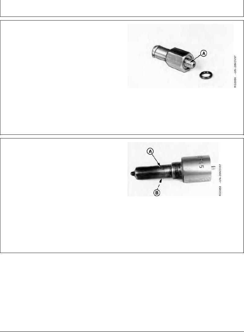
5. Inspect the M6 x1 threads (A) for general condition.
Replace connector if threads are damaged and cannot
be restored to a serviceable condition.
Inspecting Leak-off Connector
RG,RG34710,1313
1923OCT972/2
ASSEMBLE FUEL INJECTION NOZZLE
IMPORTANT: Be sure to install correct nozzle
assembly on nozzle holder. Do not
intermix different size nozzle
assemblies.
To help determine correct nozzle assembly for each
application, note markings on lower part of nozzle.
Markings on Nozzle Tip
The illustration shows a nozzle marked 7 x 0.23. The
number "7" (A) indicates the number of orifices and "0.23"
(B) indicates the size of each orifice in millimeters.
Continued on next page
RG,RG34710,1314
1923OCT971/4