
TM 5-3805-281-24-2
Hydraulic System
IMPORTANT: Trapped air suddenly compressed in a
cylinder is heated and ignites the oil
33
used for assembly causing cap seal and
3360
ring damage. Start with cylinder rod
160
retracted and the rod end filled with
clean oil. Connect the cylinder head end
and lines. Operate function to slowly
extend rod. Procedure will eliminate
most of the air and reduce the
possibility of damage.
17. Start engine.
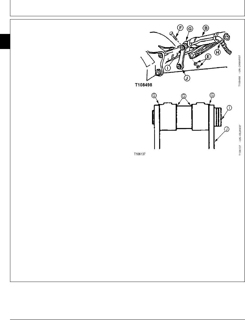
Slowly extend bucket cylinder (B) to align pin bores
so dust seals are not damaged as bucket
cylinder-to-side and center links pin (I) is installed.
18. Install washers (G) equally on each side of cylinder
rod end and side links to get minimum amount of
clearance in joint.
Install cap screw (F) and nuts (E). Tighten the nuts
against each other, not the retainer. Cap screw must
be free to turn in hole.
Bucket Cylinder-to-Link Pin M20 Cap Screw Nut--Specification
B--Bucket Cylinder
Torque ....................................................... 540 Nm (400 lb-ft) tighten nut
E--M20 Nut (2 used)
against nut, not the retainer
F--M20 Cap Screw
G--Washer (As Required)
H--Bucket Cylinder Rod End-to-Bucket Section
19. Lubricate all pivot joints. (See Track Adjuster,
Top Port Line
Working Tool Pivot, Swing Bearing, and Swing
--Bucket Cylinder Head End-to-Bucket Section
Bearing Gear Grease in Group 0004.)
Bottom Port Line
I--Side and Center Links-to-Bucket Cylinder Pin
20. Bleed air from cylinder. (See procedure in this group.)
J--Side Link
21. Check oil level in hydraulic oil tank. Add oil as
necessary. (See Hydraulic Oil in Group 0004.)
CED,OUOE026,11
1918JUN985/5
19-187