
TM 5-3805-281-24-2
Hydraulic System
CAUTION: To avoid injury from escaping fluid
under pressure, stop engine and relieve the
33
pressure in the system before disconnecting
3360
hydraulic or other lines. Tighten all connections
155
before applying pressure.
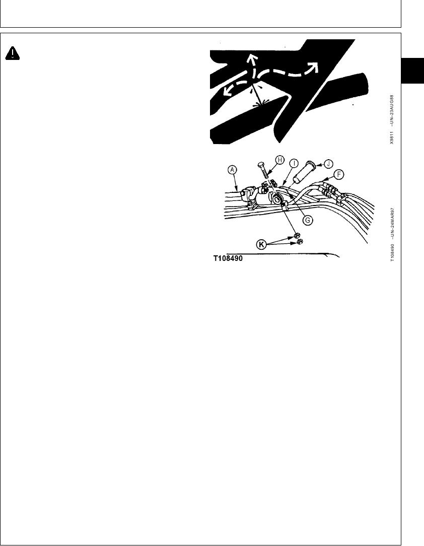
8. Disconnect hydraulic lines (F) and lubricant line (G).
9. Remove parts (H--K) to remove arm cylinder (A). Take
notice of location of washers (I) for assembly.
10. Repair or replace cylinder.
11. Install washers (I) equally on each side of cylinder
head and rod ends to get minimum amount of
clearance in joints.
12. Align pin bores so dust seals are not damaged as
arm cylinder-to-boom pin (J) is installed.
Install cap screw (H) and nuts (K). Tighten nuts
against each other, not the retainer. Cap screw must
be free to turn in hole.
Arm Cylinder-to-Boom Pin M20 Cap Screw Nut--Specification
A--Arm Cylinder
Torque ....................................................... 540 Nm (400 lb-ft) tighten nut
F--Arm Cylinder Head End-to-Arm Section
against nut, not the retainer
Bottom Port Line
--Arm Cylinder Rod End-to-Arm Section Top
13. Connect lubricant line (G) and hydraulic lines (F).
Port Line
G--Lubricant Line
H--M20 Cap Screw
IMPORTANT: Trapped air suddenly compressed in a
I--Washer (As Required)
cylinder is heated and ignites the oil
J--Arm Cylinder-to-Boom Pin
used for assembly causing cap seal and
K--M20 Nut (2 used)
ring damage. Start with cylinder rod
retracted and the rod end filled with
clean oil. Connect the cylinder head end
and lines. Operate function to slowly
extend rod. Procedure will eliminate
most of the air and reduce the
possibility of damage.
14. Start engine.
Slowly extend cylinder to align pin bores so dust
seals are not damaged as arm cylinder-to-arm pin is
installed.
Continued on next page
CED,OUOE026,10 1918JUN984/5
19-182