
TM 5-3805-281-24-2
Hydraulic System
CAUTION: To avoid injury from escaping fluid
under pressure, stop engine and relieve the
33
pressure in the system before disconnecting
3360
hydraulic or other lines. Tighten all connections
151
before applying pressure.
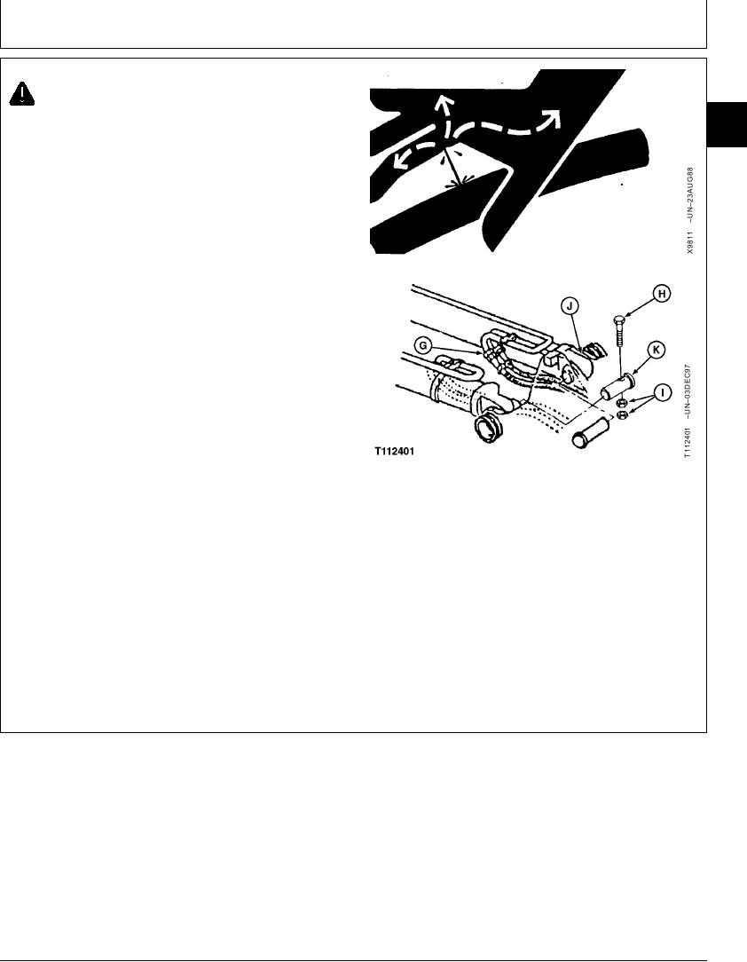
9. Disconnect lines (G) from cylinder.
10. Take notice of washer (J) locations for assembly.
Remove parts (H--K) to remove cylinder.
11. Repair or replace cylinder.
12. Install washers (J) equally on each side of cylinder
head end to get minimum amount of clearance in
joint.
13. Align pin bores so dust seals are not damaged as
boom cylinder-to-frame pin (K) is installed.
Tighten nuts (I) against each other, not the retainer.
Cap screw (H) must be free to turn in hole.
Boom Cylinder-to-Frame Pin M20 Cap Screw Nut--Specification
G--Rod End-to-Boom Section Bottom Port Line
Torque ....................................................... 540 Nm (400 lb-ft) tighten nut
--Head End-to-Boom Section Top Port Line
against nut, not the retainer
H--M20 Cap Screw
I--M20 Nut (2 used)
J--Washer (As Required)
14. Connect lines (G).
K--Boom Cylinder-to-Frame Pin
Continued on next page
CED,OUOE026,9
1918JUN984/5
19-178