
TM 5-3805-281-24-2
Hydraulic System
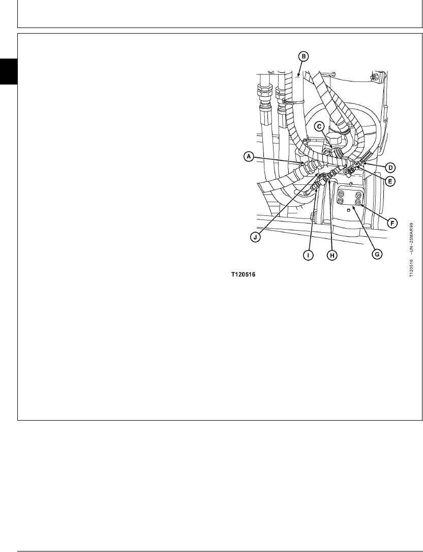
NOTE: Hoses (E) and (G) are for left boom cylinder
controlled load lowering valve only.
33
3360
5. Disconnect hoses (A, C, D, E, H and I)
148
6. Disconnect pipe (B).
7. Remove four cap screws (F), flange (G) and valve (J).
Replace parts as necessary.
Left Side Valve
A--Hose
B--Pipe
C--Hose
D--Hose
E--Hose (Left Side Only)
F--Cap Screw (4 used)
G--Flange
H--Hose
I--Hose (Left Side Only)
J--Valve
CED,OUOE020,33 1914MAR993/3
19-175