
TM 5-3805-294-10
0019
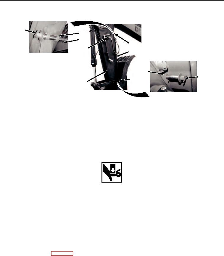
REMOVING CRUSH-ALL - Continued
3
4
2
4
6
1
5
3
5
35
HYEX01500
Figure 20.
Open Hydraulic Thumb Circuit.
NOTE
There are two auxiliary circuit shutoff valves. There is one located on both sides of the arm.
Left side shown.
32.
Open two auxiliary circuit shut off valves (Figure 20, Item 6).
33.
Remove retaining clip (Figure 20, Item 2) from pin (Figure 20, Item 3).
WARNING
Keep hands away from pin and alignment holes while thumb is being moved. Only use prybar
to push pin. Failure to comply may result in injury or death to personnel.
NOTE
Thumb may need to be repositioned multiple times with slight movements of the cylinder until
proper alignment of thumb to arm is achieved in order for pin to slide completely through.
34.
Retract or extend thumb cylinder (Figure 20, Item 1) to remove pin (Figure 20, Item 3) from thumb lock position
(Figure 20, Item 5).
35.
Install pin (Figure 20, Item 3) in storage position (Figure 20, Item 4).
36.
Install retaining pin (Figure 20, Item 2) on pin (Figure 20, Item 3).
37.
Shutdown machine. (WP 0009)
END OF TASK
END OF WORK PACKAGE
0019-15/16 blank