
TM 5-3805-294-10
0019
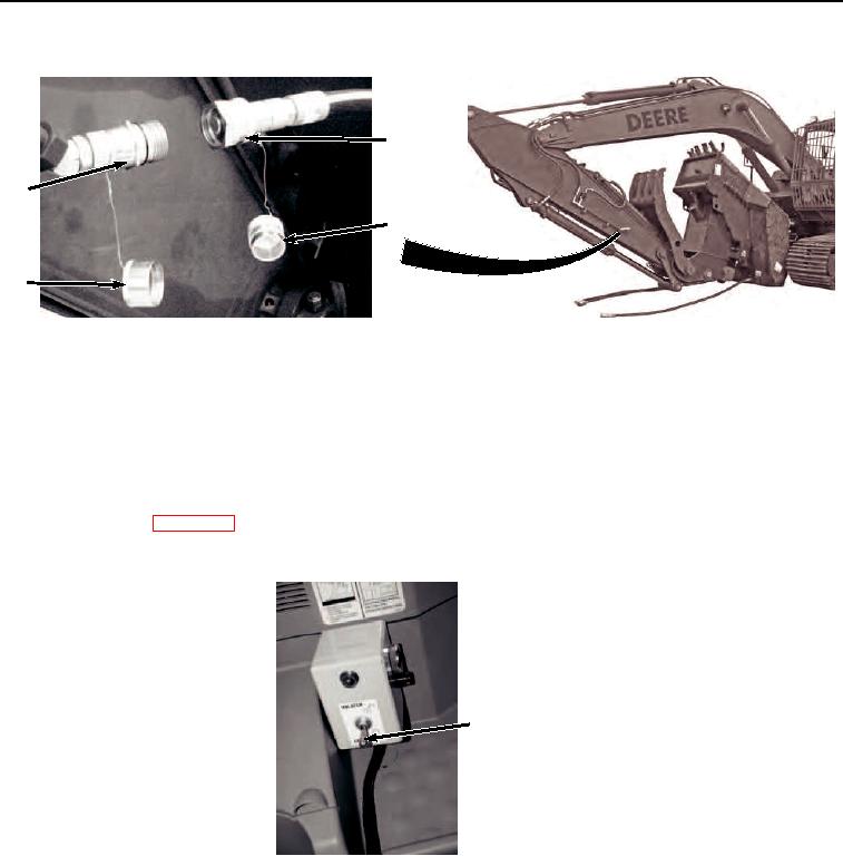
REMOVING CRUSH-ALL - Continued
18
16
17
15
HYEX01501
Figure 15. Disconnect Auxiliary Supply Line.
18.
Clean cap (Figure 15, Item 15) and plug (Figure 15, Item 17) with rag.
19.
Remove attachment quick disconnect (Figure 15, Item 18) from machine quick disconnect (Figure 15, Item
16).
20.
Install plug (Figure 15, Item 17) to attachment quick disconnect (Figure 15, Item 18).
21.
Install cap (Figure 15, Item 15) to machine quick disconnect (Figure 15, Item 16).
22.
Start machine. (WP 0007)
23.
Move quick latch switch (Figure 16, Item 7) to unlatch position.
7
HYEX03393
Figure 16. Move Quick Latch Switch.
24.
Raise boom (Figure 17, Item 12) to allow adequate ground clearance of crush-all (Figure 17, Item 11).