
TM 5-3805-294-10
0020
REMOVING IMPACT BREAKER - Continued
10.
Install plug (Figure 20, Item 16) to attachment quick disconnect (Figure 20, Item 17).
11.
Install cap (Figure 20, Item 14) to machine quick disconnect (Figure 20, Item 15).
12.
Lift and rotate safety lock pin lever (Figure 21, Item 13) to unlock position.
HYEX03406
13
Figure 21. Safety Pin to Unlock Position.
13.
Start the machine. (WP 0007)
14.
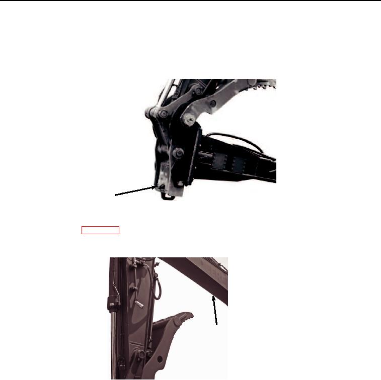
Raise boom (Figure 22, Item 8) to allow for adequate ground clearance.
8
HYEX03399
Figure 22. Raise Boom for Clearance.
15.
Move quick latch switch (Figure 23, Item 7) to UNLATCH position.