
TM 5-3805-294-10
0021
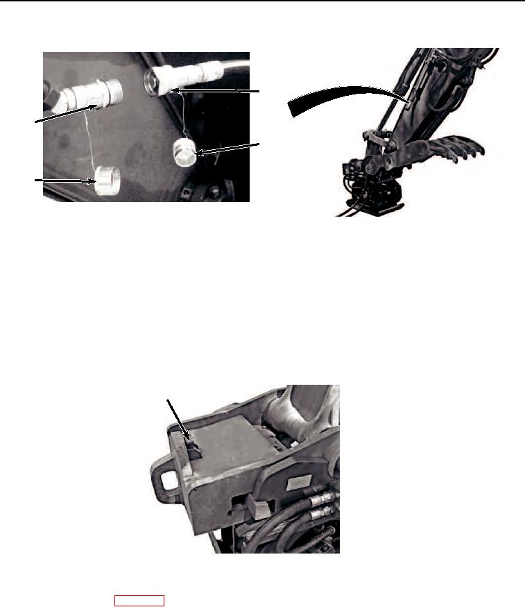
REMOVING THE COMPACTOR - Continued
17
15
16
14
HYEX03419
Figure 15. Connect Auxiliary Supply Line.
8.
Clean plug (Figure 15, Item 16) with rag.
9.
Clean cap (Figure 15, Item 14) with rag.
10.
Remove attachment quick disconnect (Figure 15, Item 17) from machine quick disconnect (Figure 15, Item
15).
11.
Install plug (Figure 15, Item 16) to attachment quick disconnect (Figure 15, Item 17).
12.
Install cap (Figure 15, Item 14) to machine quick disconnect (Figure 15, Item 15).
13.
Rotate safety lock pin lever (Figure 16, Item 13) to unlock position.
13
HYEX03421
Figure 16. Unlock Safety Lock.
14.
Start the machine. (WP 0007)
15.
Move quick latch switch (Figure 17, Item 7) to UNLATCH position.