
TM 5-3805-294-10
0084
REMOVAL - Continued
5
4
HYEX00098
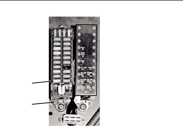
Figure 3.
Fuse Removal.
END OF TASK
INSTALLATION
CAUTION
Use only a fuse having the same amperage as noted on fuse box cover. Using a fuse with
higher amperage than specified could cause damage to the electrical system. Failure to
comply may result in damage to equipment.
NOTE
All fuses from both main and auxiliary fuse boxes are installed the same way. Main fuse box
shown.
1.
Install fuse (Figure 4, Item 5) to main fuse box (Figure 4, Item 4).