
TM 5-3805-294-23-4
0490
INSTALLATION - Continued
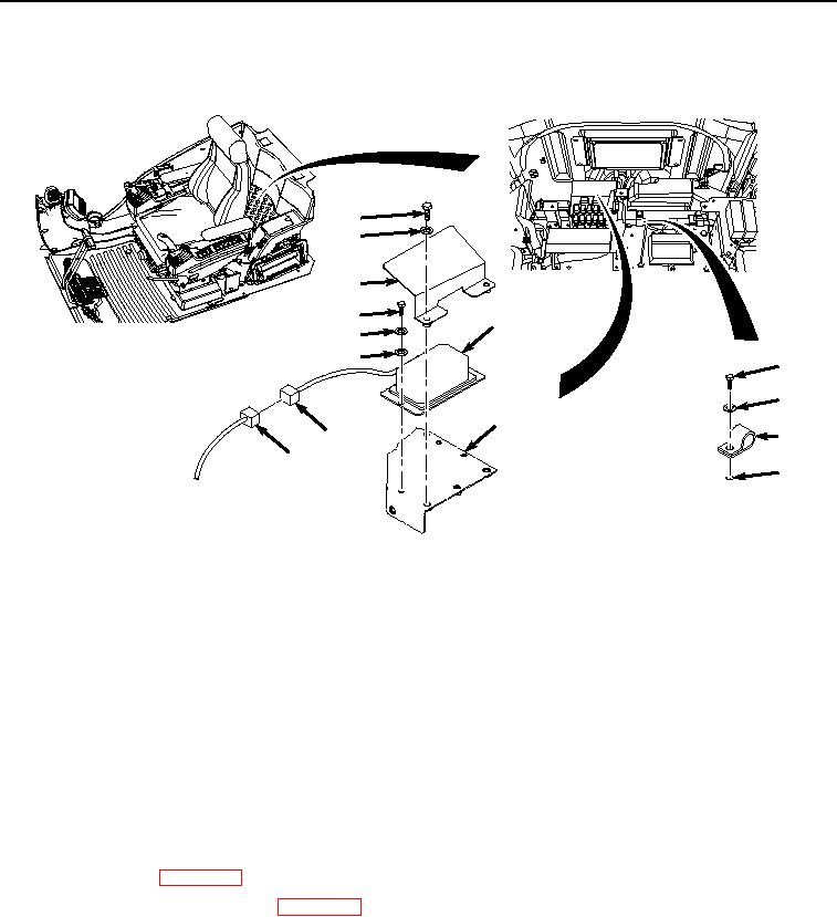
1.
Position power converter (Figure 2, Item 14) to frame (Figure 2, Item 10).
7
8
9
11
14
12
13
1
2
10
3
5
6
4
HYEX00325
Figure 2.
Power Converter Installation.
2.
Install power converter (Figure 2, Item 14) to frame (Figure 2, Item 10) with two washers (Figure 2, Item 13),
lockwashers (Figure 2, Item 12), and screws (Figure 2, Item 11).
3.
Install plate (Figure 2, Item 9) to frame (Figure 2, Item 10) with two washers (Figure 2, Item 8) and bolts (Figure
2, Item 7).
4.
Connect cab wiring harness W1 connector A8 (Figure 2, Item 6) to power converter connector A8 (Figure 2,
Item 5).
5.
Install three P-clamps (Figure 2, Item 3) to machine (Figure 2, Item 4) with three washers (Figure 2, Item 2),
and screws (Figure 2, Item 1).
END OF TASK
FOLLOW-ON MAINTENANCE
1.
Install rear tray. (WP 0566)
2.
Connect negative battery cable. (WP 0521)
3.
Perform the Standard Follow-On Maintenance Instructions. (Volume 3, WP 0384)
END OF TASK
END OF WORK PACKAGE