
TM 5-3805-294-23-4
0502
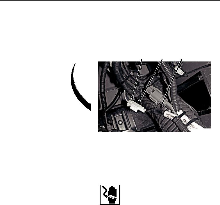
WIRING HARNESS REMOVAL - Continued
4
3
5
HYEX01258
Figure 3.
Wiring Harness Removal.
2.
Remove switch wiring harness (Figure 3, Item 5) from machine.
END OF TASK
WIRING HARNESS INSTALLATION
WARNING
Ensure electrical power is off prior to working on all electrical connections. Prior to working
on or around vehicle, remove all jewelry, such as rings, ID tags, bracelets, etc. Jewelry, and
tools can catch on equipment, contact positive electrical circuits, and cause a direct short,
severe burns, or electrical shock. Failure to comply may result in injury or death to personnel.
NOTE
Install tie wraps as required.
1.
Route switch wiring harness (Figure 4, Item 5) through machine as noted prior to removal.
2.
Connect switch wiring harness connector (Figure 4, Item 3) to cab wiring harness (Figure 4, Item 4).