
TM 5-3805-294-23-4
0503
REMOVAL - Continued
Table 1.
Relays K1 Through K14 Identification - Continued.
K12
Blower Motor (Low Speed) and Main Power Relay
K13
Blower Motor (High Speed) Relay
K14
Alternator Relay
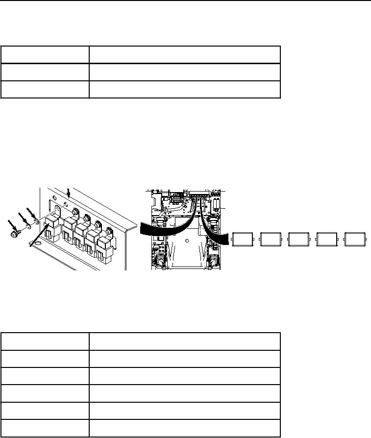
NOTE
Relays K30 through K33 and K15 are removed in the same manner. Relay K30 shown.
Relays are removed from relay holder by pressing out on plastic tabs on sides of holder
and pulling out relay.
3.
Remove screw (Figure 2, Item 3), lockwasher (Figure 2, Item 4), washer (Figure 2, Item 5), and relay K30
(Figure 2, Item 6) from bracket (Figure 2, Item 7). Discard lockwasher.
7
5
4
3
K30
K31
K32
K33
K15
6
HYEX02880
Figure 2.
Relays K30 through K33 and K15 Location and Removal.
4.
If required, remove remaining four relays and hardware in the same manner as in Step (3) above.
Table 2. Relays K30 through K33 and K15 Identification.
Relay Number
Relay Identification
K30
Right Solenoid Relay A
K31
Right Solenoid Relay B
K32
Left Solenoid Relay A
K33
Left Solenoid Relay B
K15
Start Aid Relay
NOTE
Relays K37, K36, and K20 are removed in the same manner. Relay K37 shown.
Relays are removed from relay holder by pressing out on plastic tabs on sides of holder
and pulling out relay.