
TM 5-3805-294-23-4
0504
REMOVAL - Continued
9, 10, 11
1
2
13, 14
3
15
4
8
12
6
9, 10, 11
5
7
HYEX01061
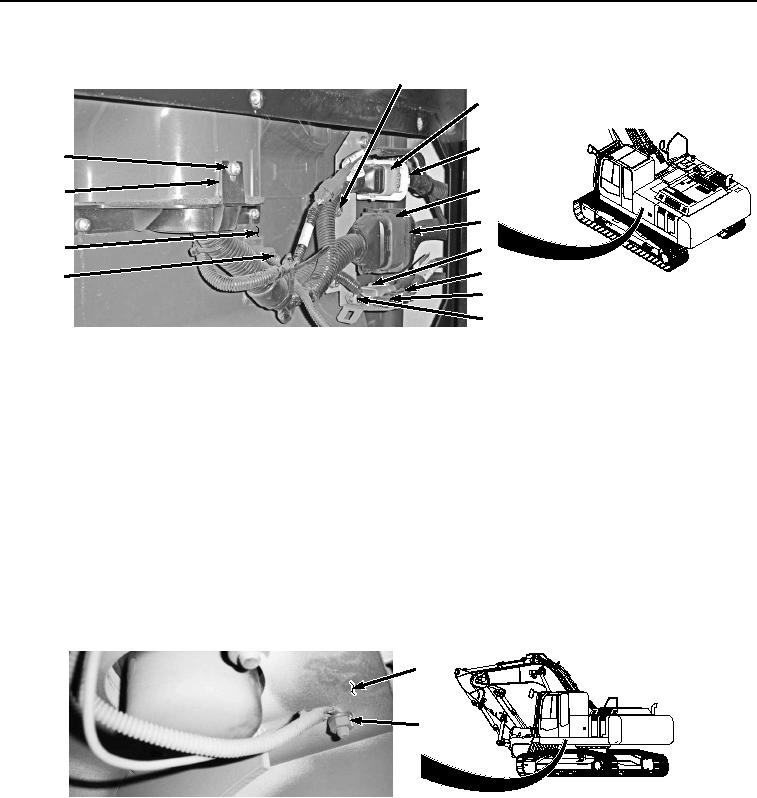
Figure 1. Machine Wiring Harness W2 Connections.
2.
Disconnect cab wiring harness W1 at connection X3 (Figure 1, Item 3) from machine wiring harness W2
connector (Figure 1, Item 4).
3.
Disconnect cab wiring harness W1 at connection X41 (Figure 1, Item 5) from machine wiring harness W2
connector (Figure 1, Item 6).
4.
Disconnect cab wiring harness W1 at connection X42 (Figure 1, Item 7) from machine wiring harness W2
connector (Figure 1, Item 8).
5.
Remove two bolts (Figure 1, Item 9), washers (Figure 1, Item 10), and clamps (Figure 1, Item 11) from cab
(Figure 1, Item 12).
6.
Remove three screws (Figure 1, Item 13), washers (Figure 1, Item 14), and cover (Figure 1, Item 15) from cab
(Figure 1, Item 12).
7.
Remove nut (Figure 2, Item 16), washer (Figure 2, Item 17), and cab wiring harness ground terminal W35
(Figure 2, Item 18) from cab (Figure 2, Item 12).
12
16
17
18
HYEX01062
Figure 2.
Ground Terminal W35.
8.
Disconnect cab wiring harness W1 at connection X22 (Figure 3, Item 19) from monitor controller wiring harness
W3 (Figure 3, Item 20).