
TM 5-3805-294-23-4
0504
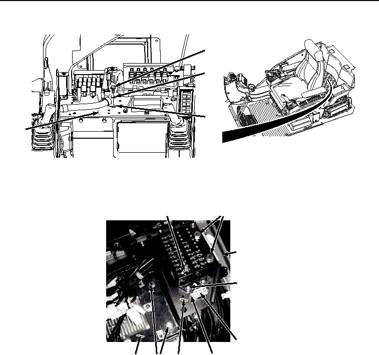
REMOVAL - Continued
58
59
60
32
HYEX01072
Figure 10. Clamp Removal.
30.
Remove two screws (Figure 11, Item 61), lockwashers (Figure 11, Item 62), washers (Figure 11, Item 63), and
connector (Figure 11, Item 64) from bracket (Figure 11, Item 65). Discard lockwashers.
70, 71
69
12
66, 67, 68
64
61, 62, 63
32
70, 71 65
HYEX01965
Figure 11.
Fuse Box Bracket Removal.
31.
Remove two screws (Figure 11, Item 66), lockwashers (Figure 11, Item 67), washers (Figure 11, Item 68), and
fuse box (Figure 11, Item 69) from bracket (Figure 11, Item 65). Discard lockwashers.
32.
Remove four bolts (Figure 11, Item 70) and washers (Figure 11, Item 71) from bracket (Figure 11, Item 32),
bracket (Figure 11, Item 65), and cab (Figure 11, Item 12).
33.
Lift bracket (Figure 12, Item 65), rotate connector (Figure 12, Item 64) and fuse box (Figure 12, Item 69) then
push fuse box and connector through bracket.