
TM 5-3805-294-23-4
0504
REMOVAL - Continued
39.
Disconnect cab wiring harness W1 at connection E3 (Figure 13, Item 80) from cab dome light wiring (Figure
13, Item 81).
40.
Disconnect cab wiring harness W1 at connection Y10 (Figure 13, Item 82) from pilot shutoff solenoid wiring
harness (Figure 13, Item 83).
41.
Disconnect cab wiring harness W1 at connection X25/AUX+ (Figure 13, Item 84) from coolant heater wiring
harness (Figure 13, Item 85).
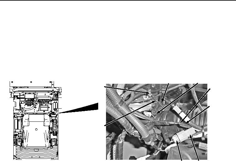
42.
Disconnect cab wiring harness W1 at connection X65 (Figure 14, Item 86) from pilot shutoff switch harness
W17 (Figure 14, Item 87).
88
89
90
92, 93, 94, 95
91
12
87
86
HYEX01079
Figure 14.
Horn, Pilot Shutoff Switch, and Ground Terminal W38 Connections.
43.
Disconnect cab wiring harness W1 at connection S13 (Figure 14, Item 88) from travel alarm cancel switch
wiring harness (Figure 14, Item 89).
44.
Disconnect cab wiring harness W1 at connection S5 (Figure 14, Item 90) from horn switch wiring (Figure 14,
Item 91).
45.
Remove bolt (Figure 14, Item 92), lockwasher (Figure 14, Item 93), washer (Figure 14, Item 94), and ground
terminal W38 (Figure 14, Item 95) from cab (Figure 14, Item 12). Discard lockwasher.
46.
Disconnect cab wiring harness W1 connector (Figure 15, Item 96) from fan reversing switch connector (Figure
15, Item 97).