
TM 5-3805-294-23-4
0504
REMOVAL - Continued
12.
Disconnect cab wiring harness W1 at connection X38 (Figure 4, Item 25) from right-hand console wiring
harness W11 (Figure 4, Item 26).
13.
Disconnect cab wiring harness W1 at connection X39 (Figure 4, Item 27) from right-hand console wiring
harness W11 (Figure 4, Item 26).
14.
Disconnect cab wiring harness W1 at connection X47 (Figure 4, Item 28) from right-hand console wiring
harness W11 (Figure 4, Item 26).
15.
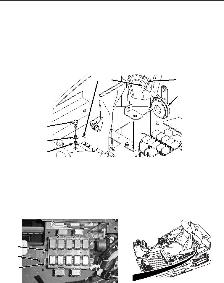
Remove bolt (Figure 5, Item 29), washer (Figure 5, Item 30), and cab wiring harness W1 ground terminal W36
(Figure 5, Item 31) from bracket (Figure 5, Item 32).
32
33
33
34
29
30
31
HYEX01961
Figure 5.
Ground Terminal W36 and Security Alarm Connections.
16.
Disconnect cab wiring harness W1 at connection H2 (Figure 5, Item 33) from security alarm (Figure 5, Item
34).
NOTE
Relay block is hard wired to and will be removed with cab wiring harness.
17.
Remove four screws (Figure 6, Item 35), lockwashers (Figure 6, Item 36), washers (Figure 6, Item 37), and
relay block (Figure 6, Item 38) from bracket (Figure 6, Item 32). Discard lockwashers.
38
32
35
36
37
HYEX01071
Figure 6. Relay Block Removal.