
TM 5-3805-294-23-4
0503
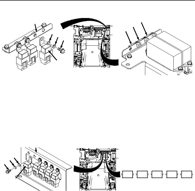
INSTALLATION - Continued
K20
12
K36
K37
10
9
8
11
HYEX02881
Figure 4. Relays K36, K37 and K20 Installation.
2.
If required, install remaining two relays and hardware in the same manner as in Step (1) above.
NOTE
Relays K30 through K33 and K15 are installed in the same manner. Relay K30 shown.
Relays are installed by inserting in holder and allowing plastic tabs on sides of holder to
lock relay in.
3.
Install relay K30 (Figure 5, Item 6) to bracket (Figure 5, Item 7) with washer (Figure 5, Item 5), lockwasher
(Figure 5, Item 4), and screw (Figure 5, Item 3).
7
5
4
3
K30
K31
K32
K33
K15
6
HYEX02880
Figure 5. Relays K30 through K33 and K15 Installation.
4.
If required, install remaining four relays and hardware in the same manner as in Step (3) above.
NOTE
Relays K1 through K14 are installed in the same manner. Relay K1 shown.
Relays are installed by inserting in holder and allowing plastic tabs on sides of holder to
lock relay in.
5.
Install relay K1 (Figure 6, Item 1) to relay block (Figure 6, Item 2).