
TM 5-3805-294-23-4
0503
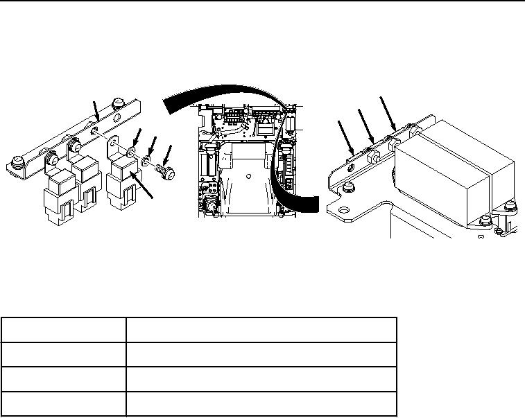
REMOVAL - Continued
5.
Remove screw (Figure 3, Item 8), lockwasher (Figure 3, Item 9), washer (Figure 3, Item 10), and relay K37
(Figure 3, Item 11) from bracket (Figure 3, Item 12). Discard lockwasher.
K20
12
K36
K37
10
9
8
11
HYEX02881
Figure 3.
Relays K37, K36, and K20 Location and Removal.
6.
If required, remove remaining two relays and hardware in the same manner as in Step (5) above.
Table 3. Relays K20, K36, and K37 Identification.
Relay Number
Relay Identification
K37
Cab Rear Work Lights
K36
Cab Front Work Lights
K20
Seat Heater Relay
END OF TASK
INSTALLATION
NOTE
Install connectors and wiring harnesses as noted prior to removal.
Install tie wraps as noted prior to removal.
Relays K36 and K20 are installed in the same manner. Relay K37 shown.
Relays are installed by inserting in holder and allowing plastic tabs on sides of holder to
lock relay in.
1.
Install relay K37 (Figure 4, Item 11) to bracket (Figure 4, Item 12) with washer (Figure 4, Item 10), lockwasher
(Figure 4, Item 9), and screw (Figure 4, Item 8).