
TM 5-3805-294-23-4
0504
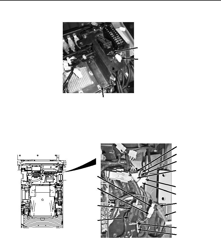
REMOVAL - Continued
69
64
65
HYEX01966
Figure 12. Fuse Box Removal.
34.
Move bracket (Figure 12, Item 65) as needed to access connections.
35.
Disconnect cab wiring harness W1 at connection X26 (Figure 13, Item 72) from auxiliary control wiring harness
W15 (Figure 13, Item 73).
72
80
81
73
76
78
77
79
82
74
83
75
84
85
HYEX01075
Figure 13. Miscellaneous Connections Under Fuse Boxes.
36.
Disconnect cab wiring harness W1 at connection X43 (Figure 13, Item 74) from auxiliary fuse box wiring
harness W13 connector (Figure 13, Item 75).
37.
Disconnect cab wiring harness W1 at connection X44 (Figure 13, Item 76) from auxiliary fuse box wiring
harness W13 connector (Figure 13, Item 77).
38.
Disconnect cab wiring harness W1 at connection M5 (Figure 13, Item 78) from windshield wiper motor wiring
(Figure 13, Item 79).