
TM 5-3805-294-23-4
0504
INSTALLATION - Continued
69
64
65
HYEX01966
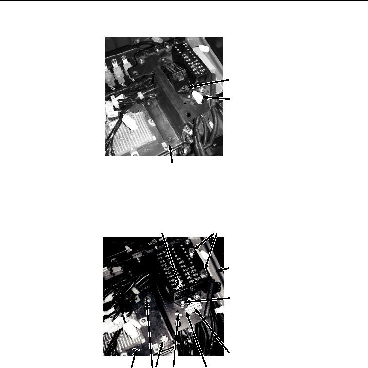
Figure 19. Fuse Box Installation.
16.
Install bracket (Figure 20, Item 65) to cab (Figure 20, Item 12) and bracket (Figure 20, Item 32) with four screws
(Figure 20, Item 70) and washers (Figure 20, Item 71).
70, 71
69
12
66, 67, 68
64
61, 62, 63
32
70, 71 65
HYEX01965
Figure 20. Bracket Installation.
17.
Install fuse box (Figure 20, Item 69) to bracket (Figure 20, Item 65) with two washers (Figure 20, Item 68),
lockwashers (Figure 20, Item 67), and screws (Figure 20, Item 66).
18.
Install connector (Figure 20, Item 64) to bracket (Figure 20, Item 65) with two washers (Figure 20, Item 63),
lockwashers (Figure 20, Item 62), and screws (Figure 20, Item 61).
19.
Install four clamps (Figure 21, Item 60) to bracket (Figure 21, Item 32) with four washers (Figure 21, Item 59)
and bolts (Figure 21, Item 58).