
TM 5-3805-294-23-4
0504
INSTALLATION - Continued
19
21
22
20
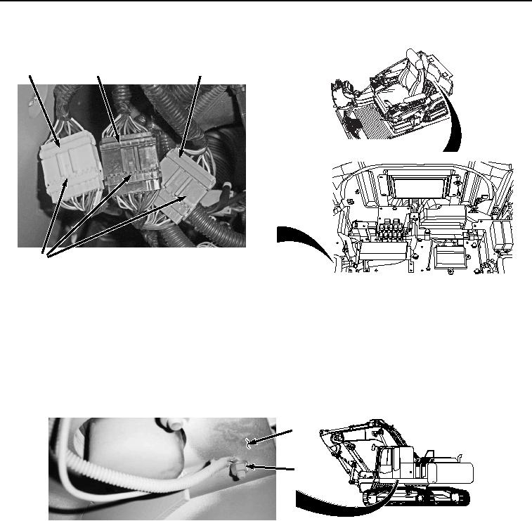
HYEX01065
Figure 28.
Monitor Controller Wiring Harness W3 Connections.
39.
Connect monitor controller wiring harness W3 (Figure 28, Item 20) to cab wiring harness W1 at connection
X23 (Figure 28, Item 21).
40.
Connect monitor controller wiring harness W3 (Figure 28, Item 20) to cab wiring harness W1 at connection
X22 (Figure 28, Item 19).
41.
Install cab wiring harness W1 ground terminal W35 (Figure 29, Item 18) to cab (Figure 29, Item 12) with washer
(Figure 29, Item 17) and nut (Figure 29, Item 16).
12
16
17
18
HYEX01062
Figure 29. Ground Terminal W35.
42.
Install cover (Figure 30, Item 15) to cab (Figure 30, Item 12) with three washers (Figure 30, Item 14) and screws
(Figure 30, Item 13).